Set the al175ulx to the desired dc output voltage by setting switch sw1 to the appropriate position refer to power supply output specification table.
Altronix power supply wiring diagram.
Altronix designs and manufactures innovative solutions that integrate disparate infrastructure and maximize overall performance and efficiency.
Keep power limited wiring separate from non power limited wiring vac 60 hz input battery wires.
Minimum 25 spacing must be provided.
This helps avoid potential damage.
The unit is specifically designed to provide the power needed by the most demanding security and access control applications.
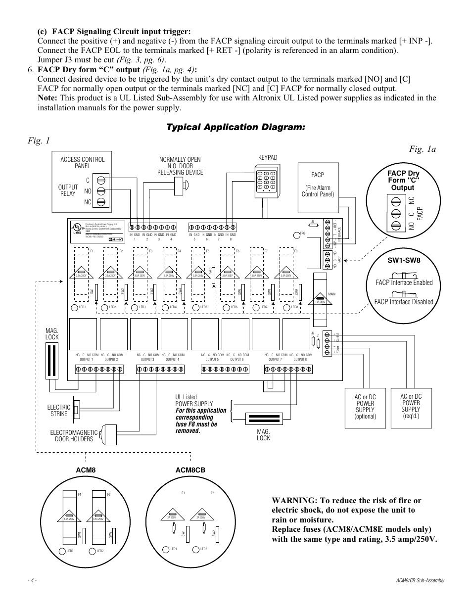
A one 1 common power input board and lock power.
To read a wiring diagram first you must know what fundamental elements are included inside a wiring diagram and which pictorial symbols are utilized to represent them.
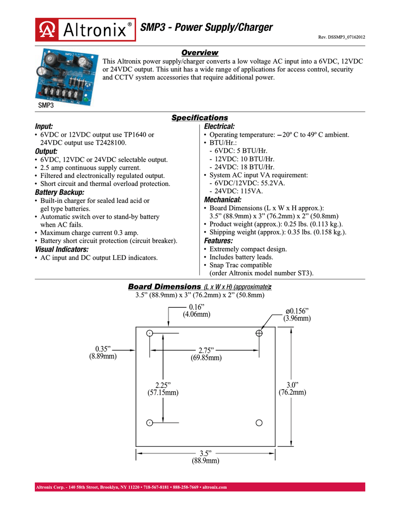
Power supply charger single output 6 12 24vdc 2 5a 24 28vac board altronix smp3 power supply charger converts a low voltage ac input into a 6vdc 12vdc or 24vdc output.
Altronix power supply wiring diagram wiring diagram is a simplified enjoyable pictorial representation of an electrical circuit.
Our comprehensive line of power products and peripherals feature the quality reliability and unparalleled customer support that have been associated with altronix for over 30 years proudly made in.
A wiring diagram is a simplified standard photographic depiction of an electrical circuit.
Eight 8 access control system trigger inputs.
It shows the parts of the circuit as streamlined shapes as well as the power as well as signal links in between the tools.
C any combination of the above.
B two 2 isolated power inputs one 1 for board power and one 1 for lock accessory power.
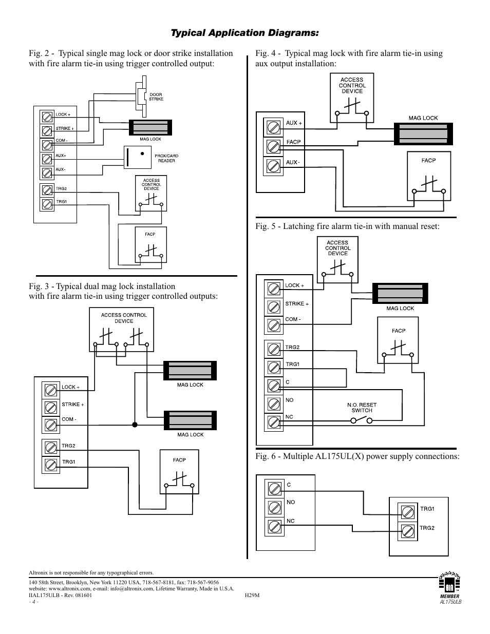
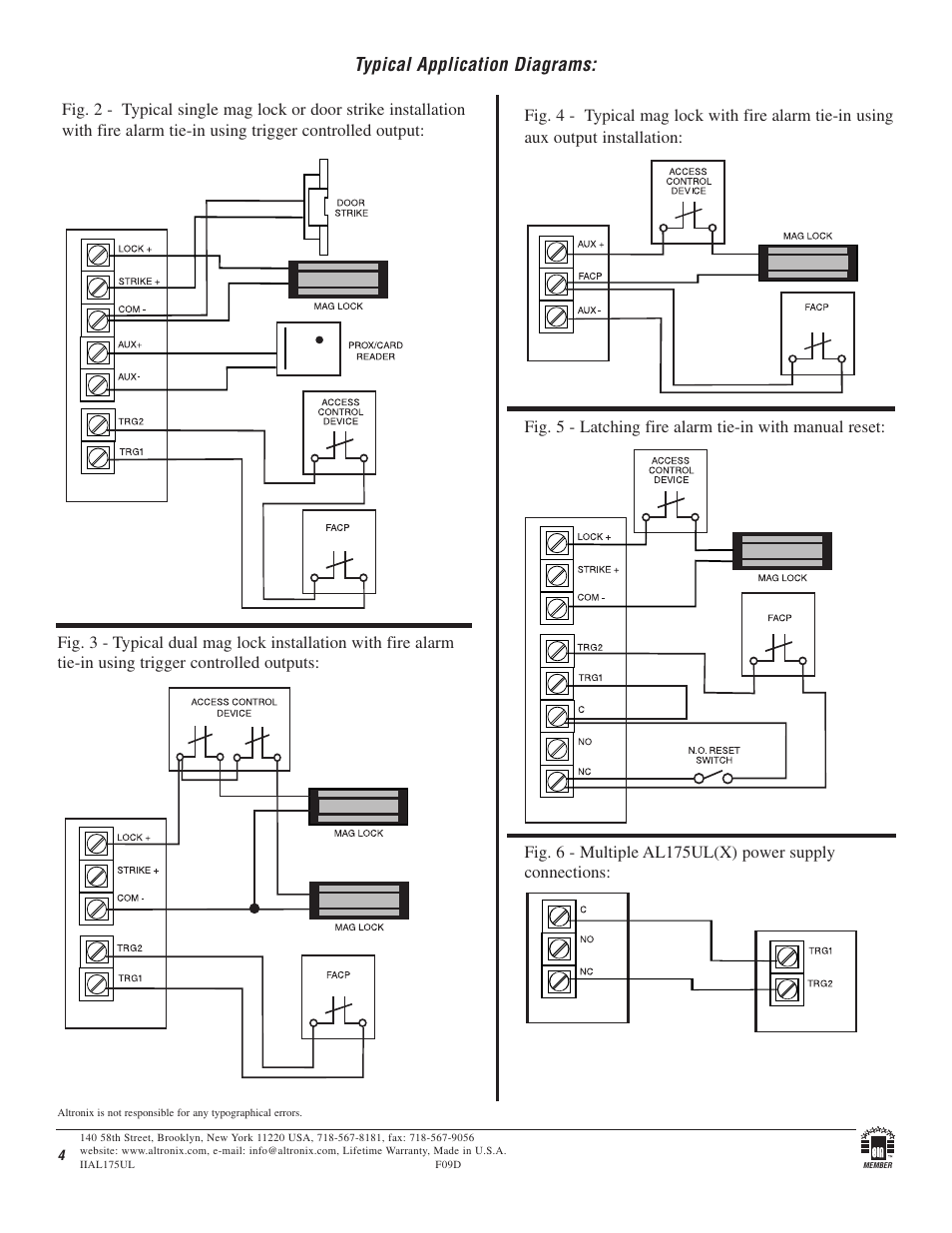
Figure 1 wiring diagram for connecting de exit devices to a ps power supply installation instructions 5 measure output voltage before connecting devices.
B eight 8 open collector sink inputs.
Collection of altronix relay wiring diagram.
Keep power limited wiring separate from non power limited wiring 115vac 60hz input battery wires.
It shows the components of the circuit as simplified shapes and the facility and signal associates amongst the devices.
It shows the elements of the circuit as streamlined forms as well as the power and signal links in between the gadgets.
Linear power supply charger single class 2 output 12 24vdc 2 5a 16 28vac board altronix lps3 linear power supply charger converts a low voltage ac input into a 12vdc or 24vdc output.
A wiring diagram is a simplified standard photographic representation of an electric circuit.
Power supply input options.
This unit has a wide range of applications for access control security and cctv system accessories that require additional power.